⚝
One Hat Cyber Team
⚝
Your IP:
216.73.216.249
Server IP:
15.204.235.159
Server:
Linux srv.techlup.co.ke 4.18.0-553.5.1.el8_10.x86_64 #1 SMP Wed Jun 5 09:12:13 EDT 2024 x86_64
Server Software:
Apache
PHP Version:
8.2.27
Buat File
|
Buat Folder
Eksekusi
Dir :
~
/
proc
/
self
/
root
/
usr
/
share
/
doc
/
svt-av1-libs
/
Docs
/
View File Name :
Appendix-Restoration-Filter.md
# Restoration Filter Appendix The restoration filter is applied after the constrained directional enhancement filter (CDEF) and aims at improving the reconstructed picture by recovering some of the information lost during the compression process. The restoration filter involves two main filters, namely a Wiener filter and a self-guided restoration filter with projection (SGRPROJ). The processing of a frame by the restoration filter proceeds by splitting the picture into restoration units. The size of the restoration units is set in the function `set_restoration_unit_size` and is set to the maximum restoration unit size (```RESTORATION_UNITSIZE_MAX```) of 256 for both luma and chroma when picture\_width\*picture\_height\>352\*288, otherwise it is set to 128. At the frame level, the restoration filter operates with one of the following modes: OFF, Wiener filter, SGRPROJ filter for the whole frame, or switching between those three modes at the restoration unit level. ## I. Wiener Filter ### 1. Description of the algorithm [To be completed] The Wiener filter is a separable symmetric filter (7/5/3-tap filters), where only three, two or one coefficient(s) for the horizontal and vertical filters are included in the bit stream due to symmetry. The constraints on the Wiener filter to reduce complexity are as follows: - The filter is separable. Let  and  be the wx1 vertical and horizontal filter kernels. - The filter kernels  and  are symmetric: =c_v(w-1-i)), =c_h(w-1-i)), i=0,1...,r-1. - The sum of the coefficients is 1:  The design of the Wiener filter proceeds in an iterative manner: - Starts with initial guess for both the vertical and horizontal filters. - Design one of the two filters while holding the second filter fixed, then repeat the process The filter is designed over windows of size 64x64 in the reference picture. The filter taps are either 7, 5, or 3 for luma and 3 or 5 for chroma. ### 2. Implementation [To be completed] **Inputs to rest\_kernel**: Output frame of the CDEF filter. **Outputs of rest\_kernel**: Restored picture, filter parameters. **Control macros/flags**: ##### Table 1. Control flags for the Wiener filter. | **Flag** | **Level** | **Description** | | ------------------- | --------- | ------------------------------------------------------------------------------------------------------------------- | | enable\_restoration | Sequence | Indicates whether to use restoration filters for the whole sequence. | | wn\_filter\_mode | Picture | Controls the quality-complexity tradeoff of the filter as a function of the encoder mode. | | allow\_intrabc | Picture | Indicates whether to enable intra block copy. The restoration filter is not active when allow\_intrabc is set to 1. | ## II. Self-Guided Restoration Filter with Subspace Projection (SGRPROJ) ### 1. Description of the algorithm The main objective behind using the SGRPROJ filter is to smooth the reconstructed image while preserving edges. The filter consists of two main components, namely a self-guided filter and a subspace projection of the reconstructed image. #### 1.1 Self-guided filter The self-guided filter feature makes use of a guide image where the objective is to transfer features in the guide image to the reconstructed picture. When the guide image is the same as the reconstructed image, the filter is called a self-guided filter. The objective in this case is to apply filtering that is a function of the spatial characteristics (variance) of the immediate neighborhood of the pixel to be filtered. The main idea behind the filter is outlined below. A filtered value  of a sample value  in the reconstructed image is generated as follows: 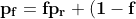\mu}) where  is the average of a small window ***w*** around  in the reconstructed picture and 0\<=  \< 1 is a function of the variance of the samples in the window ***w.*** - When the variance of ***w*** is large, then  is close to 1, and the filtered sample value is very close to  i.e. very little filtering takes place, and high frequency features (edges) in ***w*** are preserved. - When the variance of ***w*** is very small, then  is close to 0, and the filtered sample value is very close to , i.e.  is replaced by a value close to  and smoothing takes place. The figure below illustrates the main idea behind the filter.  ##### Figure 1. Example of how the variance of the area around the sample to filtered affects the selection of the self-guided restoration filter parameters. The derivation of the filter parameters is outlined below. - Compute the mean  and the square of the variance  of a (2r+1)x(2r+1) window ***w*** around the sample  in the reconstructed image. - Define  , \mu}). The parameter  is used to tune the filter. - Repeat the same computations above for every sample in the window ***w*** (or for a subset of those samples). Define **F** and **G** to be the averages of  and  computed for all samples in the window ***w*** (or for a subset of those samples), respectively. - Filtering: 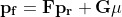 The performance of the self-guided filter is generally not sufficient to produce good quality reconstructed images. As a result, a further restoration step is considered and involves the use of subspace projection. ### 1.2. Subspace Projection The main idea behind subspace projection is as follows: - Construct two restored versions of the reference picture generated using the self-guided filter using two different (r,  ) parameter pairs. - Consider the difference between each of the two restored versions and the reference picture and consider the subspace generated by those two differences. - Project the difference between the source image and the reconstructed image into the constructed subspace. To illustrate the idea of subspace projection, consider the following column vectorized version of the corresponding pictures: -  : Source. -  : Reconstructed. -  and  : Filtered (i.e. restored) versions of  using self-guided filter based on parameters ( ) and ( ) respectively. -  : Final restored version of . (  ) is obtained by projecting (  ) onto the subspace generated by (  ) and (  )  ##### Figure 2. Illustration of the idea of subspace projection in the SGRPROJ filter. - =\alpha(X_1-X_r)+\beta(X_2-X_r)) -  - 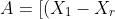(X_2-X_r)],b=[(X_s-X_r)]) -  ### 2. Implementation **Inputs to rest\_kernel**: Output frame of the CDEF filter. **Outputs of rest\_kernel**: Restored picture, filter parameters. **Control macros/flags**: ##### Table 2. Control flags for the SGRPROJ filter. | **Flag** | **Level** | **Description** | | ------------------- | --------- | ------------------------------------------------------------------------------------------------------------------- | | enable\_restoration | Sequence | Indicates whether to use restoration filters for the whole sequence. | | sg\_filter\_mode | Picture | Controls the quality-complexity tradeoff of the filter as a function of the encoder mode. | | allow\_intrabc | Picture | Indicates whether to enable intra block copy. The restoration filter is not active when allow\_intrabc is set to 1. | #### Details of the implementation The main function calls associated with the SGRPROJ filter as indicated in Figure 3 below.  ##### Figure 3. Main function calls associated with the SGRPROJ filter. The main steps involved in the implementation of the algorithm are outlined below, followed by more details on some of the important functions. #### Step 1 - Splitting the frame into segments The frame to be filtered is divided into segments to allow for parallel filtering operations on different parts of the frame. Each segment could involve more than one restoration unit. The sizes and number of segments are set as follows (see EbEncHandle.c): ```c unit_size = 256; rest_seg_w = MAX((sequence_control_set_ptr->max_input_luma_width /2 + (unit_size >> 1)) / unit_size, 1); rest_seg_h = MAX((sequence_control_set_ptr->max_input_luma_height/2 + (unit_size >> 1)) / unit_size, 1); sequence_control_set_ptr->rest_segment_column_count = MIN(rest_seg_w,6); sequence_control_set_ptr->rest_segment_row_count = MIN(rest_seg_h,4); ``` Each segment may consist of a number of restoration units. Each restoration unit is split into restoration processing units of size 64x64 for luma (```#define RESTORATION_PROC_UNIT_SIZE 64```(in EbRestoration.h)) #### Step 2 – Restoration filter search. Each segment goes through a search to identify the best SGRPROJ filter parameters for each restoration unit in the segment (```restoration_seg_search```). Loop over all restoration units in a given tile segment (```foreach_rest_unit_in_tile_seg```) - Determine the best filtering parameters for the restoration unit (```search_selfguided_restoration```) - Determine the search range for epsilon values \[start\_ep, end\_ep\] for epsilon values to use in optimizing the filter parameters, where epsilon is indicated in the description of the algorithm presented above. - Loop over the epsilon values in the range \[start\_ep, end\_ep\] - Loop over 64x64 restoration processing units in the restoration unit (apply\_sgr) - Filter all samples in the 64x64 restoration processing unit (av1\_selfguided\_restoration(\_avx2 or \_c). More details on av1\_selfguided\_restoration(\_avx2 or \_c) are included below. - Generate the projection of the (Source -Reconstructed) onto the subspace generated by (Filtered\_recon\_1 - Reconstructed) and (Filtered\_recon\_2 - Reconstructed), where Filtered\_recon\_1 and Filtered\_recon\_2 are two restored version of thereconstructed picture, and generate the corresponding projection coordinates xq\[0\] and xq\[1\], which correspond to \(\alpha\) and \(\beta\) in the description of the algorithm outlined above. (```get_proj_subspace```) - Compute the following parameters in (encode\_xq) - xqd\[0\]: Clamped value of xq\[0\] - xqd\[1\]: Clamped value of (128 - xqd\[0\] - xq\[1\]) - Perform a refinement search around the identified parameters xq\[0\] and xq\[1\] to see if any other nearby parameters provide a better filtering error. (```finer_search_pixel_proj_error```) - Keep track of the best filtering error for the restoration unit, the corresponding epsilon and (xqd\[0\], xqd\[1\]) parameters. - Increment a counter ```sg_frame_ep_cnt[bestep]``` for the identified best epsilon value from the steps above. - Return the best epsilon and (xqd\[0\], xqd\[1\]) parameters for the current restoration unit. - Filter stripes of height 64 (```try_restoration_unit_seg```) - Loop over stripes (```av1_loop_restoration_filter_unit```) - Loop over the restoration processing units in a stripe and apply filtering to each restoration processing unit using the already identified best filtering parameters for each restoration processing unit. (```sgrproj_filter_stripe```) - Compute the sse for the filtered restoration unit (```sse_restoration_unit```) The function calls associated with step 2 above are summarized in the diagram shown in Figure 4 below.  ##### Figure 4. Continuation of Figure 3 showing the function calls associated with SGRPROJ filter parameter search. #### Step 3 – Identify the best filtering mode for the whole frame - Loop over the picture planes to identify the best restoration option for each of the picture planes - Loop over all available filtering options (```RESTORE_NONE, RESTORE_WIENER, RESTORE_SGRPROJ, RESTORE_SWITCHABLE```), compute the resulting cost for using each of the options over the whole frame, and choose the best option for the whole frame. The selection is based on the rate-distortion cost of the different options. (```rest_finish_search```) #### Step 4 – Filter each restoration unit in the frame using the identified best option from step 3 above. (```av1_loop_restoration_filter_frame```) #### More details on av1\_selfguided\_restoration(\_avx2 or \_c). ```c #define MAX_RADIUS 2 // Only 1, 2, 3 allowed #define MAX_NELEM ((2 * MAX_RADIUS + 1) * (2 * MAX_RADIUS + 1)) ``` For a given 64x64 block in a restoration unit, integral images D and C corresponding to the sum of elements in the 64x64 block and to the sum of their squares, respectively, are generated. These two integral images make is very easy to compute the mean and variance of any block with arbitrary location and size in the 64x64 block. The integral images D and C are used to compute the filter parameters for each sample in the 64x64 block. The filter parameters are stored in arrays A and B. To filter a given sample, the filter parameters for neighboring samples are averaged. The filter parameters are obtained from the arrays A and B. The neighboring samples are taken from a window of size (2r+1)\*(2r+1) around the sample to be filtered, where r could be 1 or 2 (r=0 implied SGRPROJ filter is OFF). A weighted average of the neighboring filtering parameters for the neighboring samples is used in filtering the current sample, as outlined above in the description of the filter algorithm. See ```av1_selfguided_restoration_c, selfguided_restoration_fast_internal and selfguided_restoration_internal``` for the C implementation, av1_selfguided_restoration_avx2, integral_images, calc_ab_fast, final_filter_fast, calc_ab, final_filter for the avx2 implementation. ### 3. Optimization of the algorithm Both the Wiener filter and the SGRPROJ filters involve, at the restoration unit level, a search procedure for the best Wiener filter parameters and for the best SGRPROJ filter parameters. The tradeoff between complexity and quality is achieved by limiting the extent of the filter parameter search. **3.1 Wiener filter search** For the wiener filter, the search could be performed using either 3, 5 or 7 tap filters for luma, or 3 or 5 tap filters for chroma. The parameter ```cm->wn_filter_mode``` is used to specify the level of filter complexity, where increasing levels of filter search complexity are defined by considering an increasing number of filter taps for both luma and chroma, as given in the table below. ##### Table 3. Description of the Wiener filter settings for the different ```wn_filter_mode``` values. | **wn\_filter\_mode** | **Settings** | | -------------------- | ------------------------ | | 0 | OFF | | 1 | 3-Tap luma/ 3-Tap chroma | | 2 | 5-Tap luma/ 5-Tap chroma | | 3 | 7-Tap luma/ 5-Tap chroma | The encoder mode (```picture_control_set_ptr->enc_mode```) is used to specify the Wiener filter mode (```cm->wn_filter_mode```). The settings of the filter mode as a function of the encoder mode are given in the table below. ##### Table 4. Wiener filter settings as a function of encoder mode.  **3.2 SGRPROJ filter search** The search for the best SGRPROJ filter is normally performed by evaluating the filter performance for each of the sixteen different  values in the interval \[0,15\], where  is used in the outline of SGRPROJ algorithm presented above. The algorithmic optimization of the filter search involves restricting the range of  values in the search operation. The parameter ```cm->sg_filter_mode``` is used to specify different level of search complexity, where a higher value of ```cm->sg_filter_mode``` would correspond to a wider interval of  values and a more costly search. The parameter step is used to control the width of the search interval, and is given in the following table. ##### Table 5. Step parameter as a function of the sg\_filter\_mode. | **sg\_filter\_mode** | **step** | | -------------------- | -------- | | 0 | OFF | | 1 | 0 | | 2 | 1 | | 3 | 4 | | 4 | 16 | The ```sg_filter_mode``` parameter is a function of the encoder mode (```picture_control_set_ptr->enc_mode```) as indicated in the table blow. ##### Table 6. Step parameter as a function of the encoder mode.  The optimization proceeds as follows: 1. The encoder mode ```enc_mode``` specifies the SGRPROJ filter mode ```sg_filter_mode```. 2. The ```sg_filter_mode``` specifies the parameter step through the function ```get_sg_step```. 3. The interval \[start\_ep, end\_ep\] of  values to search is specified as follows (```search_selfguided_restoration```): - The  values sg\_ref\_frame\_ep\[0\] and sg\_ref\_frame\_ep\[1\] of the reference pictures are used to define the center of the interval mid\_ep as follows: ```c mid_ep = sg_ref_frame_ep[0] < 0 && sg_ref_frame_ep[1] < 0 ? 0 : sg_ref_frame_ep[1] < 0 ? sg_ref_frame_ep[0] : sg_ref_frame_ep[0] < 0 ? sg_ref_frame_ep[1] : (sg_ref_frame_ep[0] + sg_ref_frame_ep[1]) / 2; ``` - The interval limits are given by: ```c start_ep = sg_ref_frame_ep[0] < 0 && sg_ref_frame_ep[1] < 0 ? 0 : AOMMAX(0, mid_ep - step); end_ep = sg_ref_frame_ep[0] < 0 && sg_ref_frame_ep[1] < 0 ? SGRPROJ_PARAMS : AOMMIN(SGRPROJ_PARAMS, mid_ep + step); ``` ### 4. Signaling ##### Table 7. Restoration filter signals. | **Signal** | **Description** | | --------------------------------- | --------------------------------------------------------------------- | | **At the frame level** | | | frame\_restoration\_type | RESTORE\_NONE, RESTORE\_WIENER, RESTORE\_SGRPROJ, RESTORE\_SWITCHABLE | | restoration\_unit\_size | Size of restoration unit. For luma: 128x128 or 256x256 | **At the restoration unit level** | | | restoration\_type | RESTORE\_NONE, RESTORE\_WIENER, RESTORE\_SGRPROJ | | wiener\_info | Vertical and horizontal filter coefficient array vfilter and hfilter. | | sgrproj\_info | epsilon, projection parameters xqd\[0\] and xqd\[1\] | ## Notes The feature settings that are described in this document were compiled at v0.8.3 of the code and may not reflect the current status of the code. The description in this document represents an example showing how features would interact with the SVT architecture. For the most up-to-date settings, it's recommended to review the section of the code implementing this feature. ## References [1] Debargha Mukherjee, Shunyao Li, Yue Chen, Aamir Anis, Sarah Parker and James Bankoski, “*A Switchable Loop-restoration with Side-information Framework for the Emerging AV1 Video Coding*,” International Conference on Image Processing, pp. 265-269, 2017.